Design. Refine. Filter. FilterWizard® → LAUNCH NOW!



Pre-Filtered GPS Low-Noise Amplifier
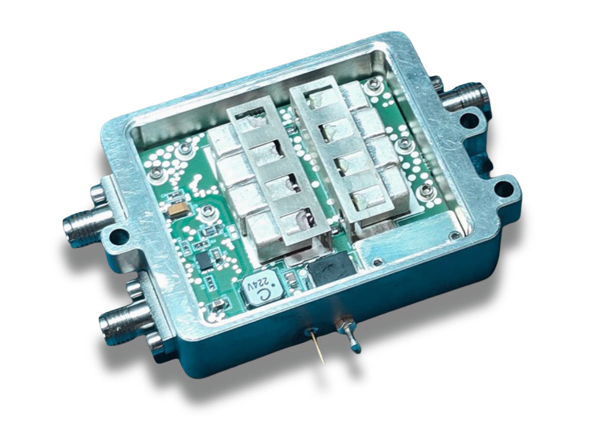
Overview
Product Name: Pre-Filtered GPS Low-Noise Amplifier
The Pre-filtered GPS LNA module will amplify GPS signals while protecting sensitive GPS receivers by filtering out-of-band interferers from a crowded EM spectrum. GPS receivers are sensitive to other near band signals which may saturate and even damage GPS receivers. This module incorporates a low-loss filter prior to the low noise amplifier stage to reduce and eliminate the signal strength of would-be interferers. This module is typically intended to mount directly to an antenna or to be used in-line to boost signal strength when there are long cable lengths between the antenna and receiver.
Applications
GPS Receiver Protection
Modern receivers are sensitive to saturation or damage by out-of-band interferers. The GPS LNA protects the receiver by removing out-of-band signals enabling operation within its linear range. The -200 variant protects against high-power signals from jammers, radars and comms that transmit near the GPS band, using a post-filter limiter that activates in the presence of high-power signals.
Inline Booster
In some cases, the GPS receiver is separated from the GPS antenna by a long cable which will increase the system noise figure. The pre-filtered GPS module can be used as an inline booster. By co-locating the module near the GPS antenna, it will provide the necessary gain to compensate for the cable loss and minimize the system noise figure. Multiple pre-filtered GPS modules can be cascaded if high gain is required.
Inline Booster with Active Antennas
Some applications make use of an active antenna which will require DC power via a coaxial bias or bias-T. In these applications, the pre-filtered GPS module has configuration options that allow DC power to be delivered to the antenna (200 mA maximum) without rewiring or reconfiguring the system. Voltage bias options 2 and 3 provide a pass-through for the DC voltage to the RF input of pre-filtered GPS module which can source power to active antennas or other upstream hardware. This allows the module to be used as inline boosters with active GPS antennas.
Coaxial Bias
Voltage bias options 1, 3 and 6 provide coaxial bias voltage options for applications requiring DC bias voltage via the center contact of the RF cable; and assists meeting EMI emission requirements
Dual-Output Option
A low-noise dual-output option filters, amplifies and divides the signal from the GPS antenna into two outputs; supporting single antenna operations where multiple GPS antennas are impractical. This is particularly useful on military platforms that require multiple GPS inputs into existing and future systems. Cascading multiple GPS LNAs can provide as many outputs as needed.
Pre-Filtered GPS LNA Module Placement
Every application is unique and where the pre-filtered GPS module should be placed in the cascaded chain must be determined by system engineering. In situations where there is cable loss and/or passive GPS antennas, the optimum placement of the pre-filtered GPS module is as close to the antenna as practical. This will allow the module to minimize the noise figure, which will help to preserve the minimum detectable signal.
For best results, the module should be placed as physically close to the GPS Antenna to minimize the cable loss between the antenna and Pre-Filtered Module.
Product Specifications
Parameter |
Specification |
Units |
||||||||
|---|---|---|---|---|---|---|---|---|---|---|
|
Band Select Center Frequency |
1176.45, 1227.6, 1575.42 |
MHz |
||||||||
|
Band Passband, min |
20.46 |
MHz |
||||||||
|
Gain Select Passband Gain ±3 dB |
16 |
19 |
22 |
25 |
28 |
31 |
34 |
dB |
||
|
|
Minimum |
Typical |
Maximum |
|
||||||
|
Noise Figure (Center Frequency) |
|
1.8 |
2.8 |
dB |
||||||
|
Output P1dB, min3 |
+3.0 |
+9.0 |
|
dBm |
||||||
|
Rejection |
||||||||||
|
L1 |
L2 |
L1/(L2/L5) |
-35 |
-40 |
|
dBc |
||||
|
1410-1495 MHz |
1050-1150 MHz |
F<1030 MHz |
||||||||
|
L1 |
L2 |
L1/(L2/L5) |
-40 |
-50 |
|
dBc |
||||
|
F<1410 MHz |
F<1050 |
F<970 MHz |
||||||||
|
Passband Input Return Loss |
-9.54 |
-17.0 |
|
dB |
||||||
|
Passband Output Return Loss |
-9.54 |
-15.0 |
|
dB |
||||||
|
Passband Group Delay |
|
±2.2 |
|
ns |
||||||
|
Standard Configuration Supply Voltage |
+4.8 |
+5.0 |
+32.0 |
VDC |
||||||
|
Low Voltage Configuration Supply Voltage4 |
+3.1 |
|
+6.0 |
VDC |
||||||
|
Standard Configuration Supply Current |
|
120 |
150 |
mA |
||||||
|
Low Voltage Configuration Supply Current4 |
|
75 |
120 |
mA |
||||||
NOTES:
1. Noise figure only guaranteed for GPS-XXXXXXX-0XX +22 dBm CW maximum input power configurations.
2. Ultimate rejection is guaranteed to 10 GHz.
3. P1dB is not guaranteed for the low-voltage 3.3 VDC configurations.
4. 3.3 VDC configurations only.
|
Altitude |
MIL-STD-810 |
Method 500, Procedure II, 200,000 feet, Operational |
|
Acceleration |
MIL-STD-810 |
20g’s in each axis, Operational |
|
EMI5 |
MIL-STD-810 |
RE102, CE102, CS101, RS103 |
|
Humidity |
MIL-STD-810 |
Method 507.4 |
|
Mechanical Shock |
MIL-STD-810 |
30g’s, 8 ms, Half Sine Pulse, Operational |
|
Sand & Dust |
MIL-STD-810 |
Method 510.4, Procedures I, II |
|
Salt Fog |
MIL-STD-810 |
Method 509.2 |
|
Temperature, Low |
MIL-STD-810 |
Method 502, Procedure II, -54°C, Operational |
|
Temperature, High |
MIL-STD-810 |
Method 501, Procedure II, +85°C, Operational |
|
Temperature, Shock |
MIL-STD-810 |
Method 503, Procedure I, -54°C to +85°C, 50 cycles |
|
Vibration |
MIL-STD-810 |
Method 514, Procedure I, Cat-12, Cat-13, Cat-15, Operational |
NOTES:
5. Conditions only met with coaxially biased option.
|
Supply Voltage |
+36VDC6 |
|
RF Input Power, CW7 |
+22 dBm |
|
Storage Temperature |
-40 to +125°C |
|
Operating Temperature |
-40 to +85°C |
|
ESD Sensitivity |
Class 1B |
NOTES:
6. Short-term transients of less than 30 seconds
7. Baseplate temperature limited to +85°C
Resources

MPG Solutions® Space Brochure

MPG Electronic Warfare Brochure

MPG Integrated Microwave Solutions Brochure
.jpg.thumb.1280.1280.png.rendition.src.1665381779359.jpg)
MPG Interference Mitigation Cosite Equipment Catalog
Contact

Subscribe to receive all MPG updates.
SUBSCRIBE
REACH US AT
Microwave Products Group
13033 Trautwein Road
Austin, TX 78737
United States
Main: 410-749-2424
support@mpgdover.com
© COPYRIGHT ©2026, MPG - MICROWAVE PRODUCTS GROUP | A DOVER COMPANY | PRIVACY POLICY | COOKIES | TERMS OF USE